Capacitive Multi-Touch Solution
Introduction
In the past, Toradex created custom capacitive Touch Drivers (single- or multi-touch) for specific devices and certain OS versions. Because there were no defined standards to connect capacitive touch devices, this resulted in having a variety of touch drivers.
The Multi-Touch Solution from Toradex gives the customer the possibility to write and maintain their own touch driver with little effort.
In the future, all capacitive touch drivers will be based on the Touch Solution. The capacitive Single-Touch and Multi-Touch drivers will not be used for new projects.
Multi-Touch Support implemented in WinCE
Windows Embedded Compact 7/2013 offers a new advanced type of support for multi-touch and gesture on specialized devices. You can get more information from here:
- Compact 7 Multi-Touch Driver and Gesture
- Touch Gestures (Windows Embedded Compact 2013)
- Touch Drivers (Windows Embedded Compact 2013)
- Comprehensive Article "Touch and Gesture"
The standard gesture recognizer supports PAN, SCROLL, SELECT, DOUBLESELECT, and HOLD. With another gesture recognizer (plug-in) additional gesture like ZOOM, ROTATE are possible. At the moment, we support only the standard gestures like PAN, SCROLL, SELECT, DOUBLESELECT, and HOLD.
Multi-Touch solution also requires extra implementation in the application itself.
Toradex Capacitive Multi-Touch Solution
Capacitive touch devices usually feature an I2C interface, while the other type of devices come with an SPI interface. The communication protocols of these devices are not standardized, so Toradex is not able to offer a capacitive touch driver that runs out-of-the-box with its Board Support Packages.
Therefore, Toradex has developed an architecture, which we call, Capacitive Multi-Touch Solution to easily adapt our capacitive multi-touch driver to any particular touch hardware.
Concept
To adapt a “standard" Multi-Touch driver to a specific capacitive multi-touch controller, the PDD layer must be modified. It includes implementation of the corresponding communication method (I2C, SPI, etc.), read of the status and touch positions out of the controller and transform it according to the CETOUCHINPUT structure.
To adapt the Multi-Touch driver to a new touch controller one needs to have a deep knowledge about Windows CE and the structure of the stream drivers, the use of the Platform builder etc. The time required to develop a driver includes taking out a lot of time for debugging (frequently downloading images, etc.) too. With the concept of the Capacitive Multi-Touch Solution, it is much easier to develop new Multi-Touch Driver.

The key components of the “Capacitive Multi-Touch Solution" are shown in the figure above:
- The "Unified Multi-Touch Driver" implemented as a driver.
- The "Multi-Touch Hardware Adaption" implemented as an application.
- The "Multi-Touch Hardware Adaption" communicates with Unified Multi-Touch Driver with the help of I/O control codes (IOCTLs).
The “Unified Multi-Touch Driver" itself is part of the Kernel. As opposed to most of the other drivers, the “Unified Multi-Touch Driver" makes no hardware access to the "Multi-Touch Device" and any other hardware.
The “Multi-Touch Hardware Adaption" runs as an application. It communicates with the "Multi-Touch Device" with or without using the standard Toradex Libraries. The main job of the “Multi-Touch Hardware Adaption" is to read statuses and touch positions from the “Multi-Touch Device" and send it to the “Unified Multi-Touch Driver".
The main advantage of this concept is that the whole communication to the “Multi-Touch Device" is implemented as an application. Because we offer a source code example of the “Multi-Touch Hardware Adaption", a customer can easily adapt this example to another “Multi-Touch Device".
Unified Multi-Touch Driver
The “Unified Multi-Touch Driver" itself is part of the Kernel. Instead of reading the statuses and the touch positions from the touch devices, the “Unified Multi-Touch Driver“ reacts on receiving of the IOCTL code “IOCTL_SET_TOUCH_EVENT".
A data block of the type TCHINPUT is sent together with the IOCTL code. This data block is well formatted so that the “Unified Multi-Touch Driver" can send it to the MDD layer without any conversion. An IOCTL event is sent to the MDD layer immediately. Therefore, the touch event rate depends on the “Multi-Touch Hardware Adaption".
Installing Unified Multi-Touch Driver
Before installing this driver, no other Touch Driver (single or multi) should be installed. To Install the driver, copy the File “UnfdMultiTchDrv.cab" to a Colibri (Desktop, Temp folder etc.) and execute it.The following screen will pop up:

After confirming (OK button) the driver files “UnfdMultiTchDrv.dll",“tchproxy.dll", and “tchcal.dll" are copied to “\FlashDisk\System“ and all necessary entries in the registry are made.
Save the registry before reboot (Start->ColibriTools->SaveReg).
Check Installed Driver and Registry Settings
The “Unified Multi-Touch Driver" sends messages to the debug output port. To see them, a terminal must be connected to the debug output port and debug output must be enabled in the boot loader.
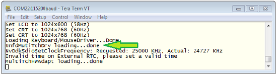
If the driver is loaded, then somewhere in the boot log output (see the image above), you will receive the following message:
“UnfdMultiTchDrv loading…done"
“done" indicates the driver is correctly loaded and running. If “done" is missing or replaced with an error message, then the driver has stopped working and is not loaded.
Virtual Touch Button Feature
The virtual touch button feature helps the customer to configure part of touch sensitive area as the button and an event could be assigned. Whenever finger/touch pen is touched on virtual touch button area, it will generate assigned event.
Cursor Area

- The Cursor Area can be smaller the Touch Sensitive Area.
- Touches inside this area are passed to GWES as touch events.
- The origins of the touch area and the display can be different.
Virtual Keys, Touch Buttons

- One or multiple Touch Buttons can be predefined in the button area by registry settings.
- If a Button Area is touched then the predefined key code is sent like a key is pressed on a keyboard.
Virtual Button Registry Setting

The panel definition is defined with the registry key
For WinCE 6
[HKEY_LOCAL_MACHINE\Drivers\BuiltIn\Touch]
For WEC7 and WEC2013
[HKEY_LOCAL_MACHINE\Drivers\Touch]
with the values for:
- The size of the Touch Sensitive Area.
- The Cursor Area.
- Button Areas (optional).
- The Touch Event.
Touch Sensitive Area
The size of the Touch Sensitive Area is depending on the used Touch Panel and the setup of the used Touch Controller Chip.
Normally, the Touch Sensitive Area (refer above picture) and the setup of the Touch Panel/Controller are defined and documented by the manufacturer of the display/touch product. The position of the origin, the mechanical dimensions and the maximal count of dots for the X and Y axis are shown in the datasheet of the Display/Touch product (Please Note: the origin is not always on the upper left corner).
With this information, the endpoint (EPTouchX, EPTouchY) can be defined and all other start points and end points (e.g. Cursor Area) can be defined as fraction of these endpoints.
Note: When doing the calibration, please use the actual touch-sensitive area on EPTouchX, EPTouchY, EPCurX, EPCurY.
Cursor Area
It is possible to define a Cursor Area (refer above picture) to control the cursor on the display. Any finger movements within this Cursor Area are transformed to cursor movements on the display. The vertexes of the Cursor Area correspond to the vertexes of the display.
The start point (SPCurX, SPCurY) and the end point (EPCurX, EPCurY) are defined as fraction of the Touch Sensitive Area.
The orientation of the X and Y axis always does not correspond to the orientation of the display.
Definition of “CapTouchMapping"
The Touch Sensitive Area and the Cursor Area are defined with the registry value “CapTouchMapping". "CapTouchMapping" is a comma separated string with 6 numbers:
"CapTouchMapping"   =        "799,    479,    36,    62,    634,    399"
       Order                  (1)     (2)    (3)    (4)     (5)     (6)
| Order | Name | Description |
|---|---|---|
| (1) (2) | EPTouchX, EPTouchY | The endpoint of the Touch Sensitive Area |
| (3) (4) | SPCurX, SpCurY | The start point of the Cursor Area |
| (5) (6) | EPCurX, EPCurY | The end point of the cursor area |
Button (optional)
If a finger touches one of the predefined Button Area (refer above picture) then, the corresponding virtual key code is sent. The behavior is similar to the keyboard.
The coordinates of the Buttons Areas are given in touch controller coordinates and is normally outside of the Cursor Area.
Note: When touching multiple virtual buttons, first key up event of previous virtual button will be sent and then new virtual button key down event will be
sent.
Example: When touching Key A, Key A down event will be sent; while touching Key B, Key A up Event and then Key B down event will be sent to GWES. While releasing Key B, Key B Up event will be sent and then while releasing Key A, nothing will be sent to GWES.
The Buttons are defined in the registry with the value
“TouchButtonX" X is a decimal number starts with “0" and can go up to “49".
"TouchButtonX" is a comma separated string with 5 numbers:
"TouchButton0"  =       "500,    100,    599,    179,    27"
        Order            (1)     (2)     (3)     (4)    (5)
| Order | Number Name | Description |
|---|---|---|
| (1) (2) | SPButX, SPButY | The start point of the button area |
| (3) (4) | EPButX, EPButY | The end point of the button area |
| (5) | Key Code | Virtual key code to send if the button is hit by finger. Please refer Virtual-Key Codes (Windows CE 5.0) and Virtual-Key Codes pages |
For example the Buttons for above picture are defined as:
"TouchButton0"="500,100,599,179,27"
"TouchButton1"="500,200,599,279,65"
"TouchButton2"="500,300,599,379,66"
Get Physical Touch Coordinates by Display on Console
If user not able to predict what would be intended virtual button physical touch coordinates, then this below registry helps to find the raw touch physical values about to configuring the virtual button.
"RawTouchDataOnConsole"=dword:00000000
Please set this registry key value to 1, save registry and then reboot the system. After boot when accessing touch screen, the actual raw touch points will be shown on the display console as shown in below picture and also in the serial debug messages.

When this bit is active, touch event won’t send to GWES. This bit will be cleared automatically when reading as 1. So the next boot the actual touch events will work.
Configuring Number of Multi-Touch Points Supported
This registry is used to specify the maximum number of multi-touch points supported by the driver to the upper layer.
"MaxTouchPoints"=dword:00000002
The possible values are 1 to 5.
Default values:
WEC7 and WEC2013 – 2 points.
WinCE6 – 1 point.
Note: Windows CE 6 supports single point touch only, so this registry is not used for Windows CE6.
Debug Messages Control
If the touch screen is not working as intended, then please try to debug the issue using registry mentioned below:
"EnableDebugMsgs"=dword:00000001.
Please set this registry key value to 1 and save registry and then reboot the system. Please log the serial debug messages when reproducing the issue and send us an email with log to support@toradex.cn to get support from our engineers.
Registry settings
A detailed description of the following settings can be found at MSDN.
[HKEY_LOCAL_MACHINE\Drivers\Touch]
DriverName      Defines for loading the multi touch driver
Prefix
Dll
Flags
Index
Order
IClass          ; IClass for touch driver class
Priority256     ; Priority of the driver

[HKEY_LOCAL_MACHINE\HARDWARE\DEVICEMAP\TOUCH]
DriverName      ; Proxy Driver

[HKEY_LOCAL_MACHINE\SYSTEM\GWE\TouchProxy]
DriverLoadTimeoutMs         ;How long touch proxy will wait for loading the touch driver to load
For example, the settings for all the Colibri and Apalis modules running Windows Embedded Comapct 7:
[HKEY_LOCAL_MACHINE\Drivers\Touch]
"DriverName"="UnfdMultiTchDrv.dll"
"Prefix"="TCH"
"Dll"="UnfdMultiTchDrv.dll"
"Flags"=dword:8           ; DEVFLAGS_NAKEDENTRIES
"Index"=dword:1
"Order"=dword:25
; IClass = touch driver class & power managed device
"IClass"=multi_sz:"{25121442-08CA-48dd-91CC-BFC9F790027C}",
                  "{7119776D-9F23-4e4e-9D9B-9AE962733770}"

;Priority256"=dword:28    ; touch is priority = 40
"CapTouchMapping"="799,479,36,62,634,399"
"TouchButton0"="500,100,599,179,27"
"TouchButton1"="500,200,599,279,65"
"TouchButton2"="500,300,599,379,66"
"MaxTouchPoints"=dword:00000002
"EnableDebugMsgs"=dword:00000000
"RawTouchDataOnConsole"=dword:00000000

[HKEY_LOCAL_MACHINE\HARDWARE\DEVICEMAP\TOUCH]
"DriverName"="tchproxy.dll"

[HKEY_LOCAL_MACHINE\SYSTEM\GWE\TouchProxy]
; how long touch proxy will wait for touch driver to load
"DriverLoadTimeoutMs"=dword:1388 ; 5 seconds
Uninstall Driver
The easiest way to uninstall the driver is by using the following sequence:
“Start->Settings->Control Panel->Remove Program"
Please Note: On the certain combination of Windows CE/Windows Embedded Compact and module types, it is not possible to uninstall the driver in this way. You will need to manually uninstall the driver.
- Replacing the “UnfdMultiTchDrv.dll"
Before the “UnfdMultiTchDrv.dll" in the directory “\FlashDisk\System“ can be replaced with a new version, rename the existing DLL and restart the device(a loaded DLL can be renamed but not erased). After a restart, copy the new driver DLL in the directory and delete the renamed DLL. After the next restart, the new driver DLL will be loaded.
- Uninstall manually
Delete all registry entries of the Registry settings section with the help of the registry editor.
“Start->Programs ->ColibriTools ->RegEdit"
Restart the device. The DLL files in “\FlashDisk\System“ can be deleted after the reboot.
Multi-Touch Hardware Adaption
The "Multi-Touch Hardware Adaption" runs as an application. After booting the application setups, the I/O signals (e.g. reset, interrupt, etc.), establishes the communication to the “Multi-Touch Device" and sends the necessary telegrams to initialize the touch device.
Additionally, the communication channel to the “Unified Multi-Touch Driver" is open. After that, the application waits for touch event from the touch device. If this happens, then the application gets the status and the touch position(s) from the touch device and converts it to the “TCHINPUT" data block and send it as an IOCTL code (call DeviceIoControl(....); ) to the “Unified Multi-Touch Driver".
How often the touch events are reported depends on the “Multi-Touch Hardware Adaption" application (polling) or the “Multi-Touch Device" itself or a combination of it.
Another feature of this application is to test the communication of touch device and start a recovery sequence, if necessary. To store some settings in the registry or an ini-file lends the possibility of writing a more generic “Multi-Touch Hardware Adaption".
Install a Multi-Touch Hardware Adaption
There is a ready-to-run “Multi-Touch Hardware Adaption" for the “Capacitive Multi-Touch Display" set. The “Hardware Adaption" is a normal application which can be started manually or automatically after booting. The pre-condition is that the “Unified Multi-Touch Driver" is installed and run.
- Source code download and documentation is available here.
Check Adaption program and Registry Settings
The “Hardware Adaption" sends messages to the debug output port. To see them, a terminal must be connected to the debug output port and debug output must be enabled in the boot loader.
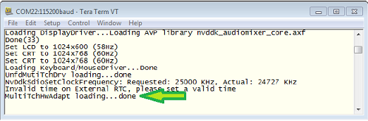
After starting the “Hardware Adaption", a message (see the image above) is printed to the debug port: MultiTchHwAdapt loading…done “done" indicates that the hardware adaption has been correctly executed. If “done" is missing or is replaced with an error message, then the hardware adaption has stopped working.
Registry Settings
This registry setting allows configuring the “Hardware Adaption" according to the wiring.
[HKEY_LOCAL_MACHINE\Software\Toradex\MultiTchHwAdapt]
Int_Pin           SODIMM (1) or MXM3 (2) pin number of the interrupt signal
Int_Signal_Inv    Interrupt active signal level (3)
Reset_Pin         SODIMM (1) or MXM3 (2) pin number of the reset signal
Reset_Post_Delay  Delay after the Reset Signal passive and the start of the initiation sequence
Reset_Line_Inv    Reset active signal level (3)
I2CSpeed          I2C speed 1 = 100kB, 2 = 400kB
I2CAddress        I2C address of the touch controller
HwAdaptPriority   Priority of the Hardware Adaptation process
(1) Pin number of the Colibri modules.
(2) Pin number of the Apalis modules.
(3) 0 or 1 (Please refer touch controller datasheet).
If a registry entry is missing, the “Hardware Adaption" uses the following default value:
Int_Pin          = 133
Int_Signal_Inv   = 0
Reset_Pin        = 127
Reset_Post_Delay = 300
Reset_Line_Inv   = 0
I2CSpeed         = 2 ( 400kB)
I2CAddress       = 16 (0x10)
HwAdaptPriority  = THREAD_PRIORITY_ABOVE_NORMAL
For example, the following registry entry shows the settings to connect "Capacitive Multi-Touch Display Fusion" to a "Colibri Evaluation Board" using "Colibri T20 Module".
[HKEY_LOCAL_MACHINE\Software\Toradex\MultiTchHwAdapt]
"Int_Pin"=dword:00000085
"Int_Signal_Inv"=dword:00000000
"Reset_Pin"=dword:0000007F
"Reset_Post_Delay"=dword:00000064
"Reset_Line_Inv"=dword:00000000
"I2CSpeed"=dword:00000002
"I2CAddress"=dword:00000010
"HwAdaptPriority"=dword:00000028
Also make sure to correctly setup the display settings using the following links:
Touch Calibration: The Unified Multi-Touch driver uses the calibration data generated by the standard calibration tool:
Start->Settings->ControlPanel->Stylus
The calibration data is stored at:
[HKEY_LOCAL_MACHINE\HARDWARE\DEVICEMAP\TOUCH]
Information about the touch calibration can be found at the MSDN.
Bringing up the Fusion Touch Panel
- Proper connection between the touch device and carrier board needs to be done. Please check the carrier board connection details here.
- Please refer to the details listed here to test the touch panel.
Run Application
- To autorun the application “Hardware Adaption Fusion", copy the application file “*.exe" in the directory “\FlashDisk\AutoRun“.
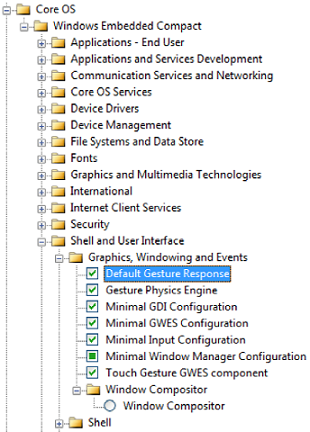
Note: The gesture feature may not be enabled in all the Toradex standard images. If you need these features get in touch with us or enable the feature in the Platform Builder catalog. If you build your own image, then these features must be enabled in the Platform builder catalog as shown in the image below.