VFxx Recovery Mode
Make sure there is no SD card inserted in the carrier board in order to enter recovery mode properly
If your module still boots, you can use the boot loader to flash your operating system. Refer to the OS specific article how to flash an image.
In case your module doesn't boot at all, you can download the boot loader directly into the modules memory using the serial port UART_A. This article shows how to this.
VF50/61
Connect the Module to your Development PC
The Colibri VFxx modules support serial recovery only using UART_A. Serial recovery requires hardware flow control with RTS/CTS signals. As the boot ROM is able to keep up with the incoming data the flow control signals can simply be bridged if required. However we recommend to use RTS/CTS whenever possible. When starting the serial downloader utility remember whether you have RTS/CTS connected or bridged.
Colibri Evaluation Board
Depending on JP17/19 (and JP20/JP21 if you use a Carrier Board with V3.2 and later) connect the serial debug console to the bottom X25 using a null modem RS-232 cable or X27 using a regular USB cable.
Note on Colibri Evaluation Board as Carrier Board
Colibri Evaluation Board 3.2
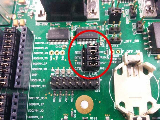
RS-232 Connector (X25, lower connector): JP17/JP19/JP20/JP21 must not be on FTDI. When connecting to PC, make sure your serial port is RTS/CTS capable (most USB-to-RS232 converter are).
Recommended: FTDI On-board USB-to-UART converter (X27): JP17/JP19/JP20/JP21 must be on FTDI. RTS/CTS are connected to the FTDI, hence hardware flow control can be used. RTS/CTS must not be shortened on module side.
Colibri Evaluation Board 3.1
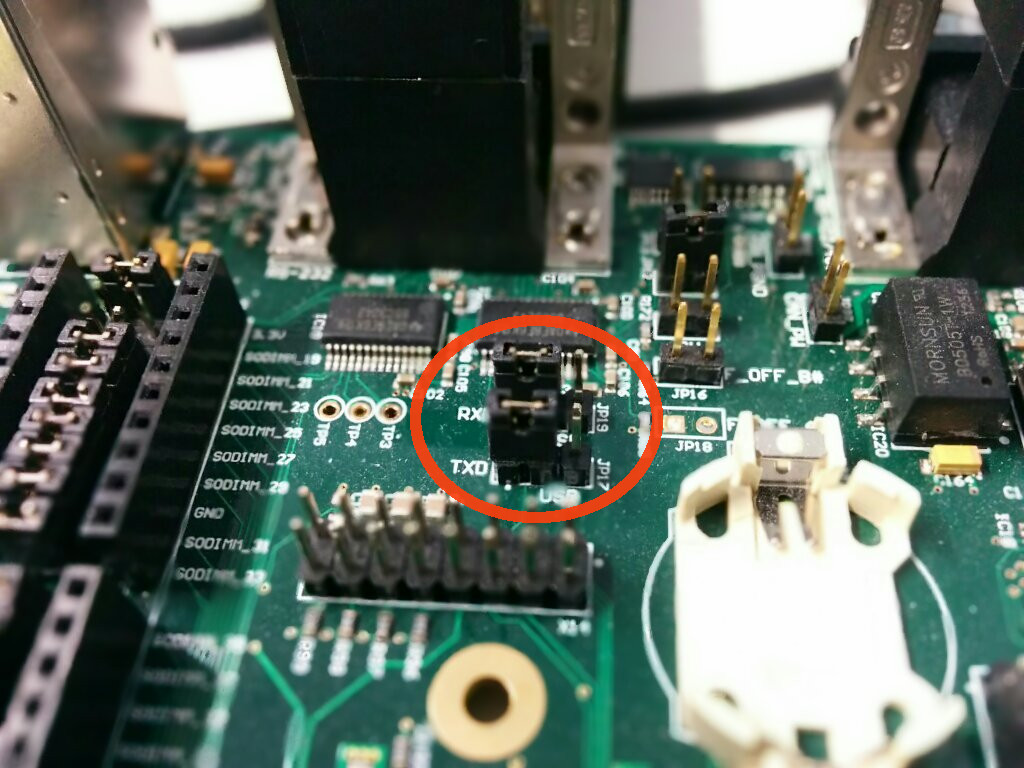
FTDI On-board USB-to-UART converter (X27): JP17/JP19 must be on USB. RTS/CTS must be shortened on the module side (this is required since RTS/CTS are NOT connected to the FTDI).
Recommended: RS-232 Connector (X25, lower connector): JP17/JP19 must not be on USB. When connecting to PC, make sure your serial port is RTS/CTS capable (most USB-to-RS232 converter are).
Iris Carrier Board
Connect UART_A on X13 to your PC.
Note on Iris as Carrier Board
- When connecting to PC make sure your serial port is RTS/CTS capable (most USB-to-RS232 converters are). However if you only have an RX/TX capable serial port (albeit still at valid RS-232 voltage levels of course) that will work as long as CTS gets properly asserted (e.g. put to a voltage level of between 3 and 15 volts) or just bridged to RTS. Refer to the Iris Carrier Board Peripherals article how to get a cable.
Aster Carrier Board
Connect the Micro USB (X4) to your PC. It functions both as a power supply and as UART_A port.
Enter recovery mode
There are 3 different methods to enter recovery mode using hardware mechanisms. While alternative 3 is more generic, it is usually a bit clumsier to execute.
Follow precautions for handling electrostatic sensitive devices (ESD)
Iris Carrier Board
Make sure the board is turned off.
Connect the 2 pads (Pins 1 and 2 from JP1) as shown in the picture
You can use scissors, tweezers, a paper clip or whatever you have at hand to short circuit the pads. You should not make a permanent short-circuit by e.g. soldering the pads together.
")
- Power on the board and, only after that, remove the short circuit.
The short circuit should be held only while the board is turning on
Colibri Evaluation Board
- Make sure the board is turned off.
- Press and hold the Recovery Mode button (SW9)
")
- Power on the board while keep pressing the Recovery Mode button for additional 1-2 seconds.
Using Reset doesn't work! This is since the Vybrid SoC samples the boot mode strapping pins only once when it gets powered-up.
Other Boards
- Make sure the board is turned off.
- Shorten the pads on the picture.
You can use scissors, tweezers, a paper clip or whatever you have at hand to short circuit the pads. You should not make a permanent short-circuit by e.g. soldering the pads together.
")
- Power on the board and, only after that, remove the short circuit.
The short circuit should be held only while the board is turning on
Run recovery utility
The serial recovery utility uses the serial download protocol used on other NXP/Freescale devices as well, hence the name imx_uart. For a more detailed instruction refer to the operating specific articles.
Note: After using the boot loader (after the module has been re-flashed) the module needs a power cycle! When using reset only the module will again switch to recovery mode. The reason is that the Vybrid SoC stores the flag "enter recovery mode" across a reset no matter if it was a hardware or software reset. The only way to clear the "enter recovery mode" flag is to power the module off and back on.
Linux Machine
The utility imx_uart is called by our update shell script:
$ ./update.sh -d /dev/ttyUSB0
In case RTS/CTS are not connected, use the parameter -n:
$ ./update.sh -n -d /dev/ttyUSB0
This downloads U-Boot to the modules memory and starts it from there.
On the same serial connection a serial console should appear after downloading the boot loader, which you can access by using a console application like screen or minicom.
The next steps are similar to the conventional flashing procedure. However, since the boot loader did not work anymore it is likely that there is something wrong with the initial boot configuration block (BCB). To recreate the BCB use the commands described in the Flashing from Scratch chapter of the Flashing Embedded Linux to Vybrid Modules article.
Windows Machine
The imx_uart utility and all the files required to recover a module from a PC running windows are included in the OS image download, in a folder of the zip file named "recovery"
The imx_uart utility can't use COM ports higher then COM9 with the commonly known syntax. There are two solutions:
You can change COM port index going into device manager and double clicking the COM port. Click on port settings tab and then click the advanced button. There is a setting called COM Port Number and you can change it there.
Instead of naming the port COMxx: , name it \\.\COMxx
To download u-boot (to flash/restore Linux image)
$ imx_uart.exe COMX: .\vybrid_uboot.conf
To download e-boot and flash/restore Windows CE:
$ imx_uart.exe COMX: .\vybrid_eboot.conf
Where COMX: is the name of your serial port.
In case RTS/CTS are not connected, use the parameter --no-rtscts. This time, we use a port number >= COM10 in the example:
$ imx_uart.exe --no-rtscts \\.\COMXX .\vybrid_eboot.conf
Flashing the image
For the steps required to completely restore the system as soon as the boot loader is running on the target, refer to one of these articles based on your desired operating system: