Txx Recovery Mode
Make sure there is no SD card inserted in the carrier board in order to enter recovery mode properly
On the Apalis Txx / Colibri Txx, the shared USB Client/Host port can be used to download a new OS image. This is only required if the Bootloader doesn't boot anymore. If your module still boots, you can use the Update Tool (Only for Windows CE at the moment).
Instructions are also available as video. Check our reprogramming guide.
To do so successfully, it is necessary to perform the following steps.
Select which tab suits your setup
Colibri T20
Connect the Module to your Development PC
- When the Colibri T20 module enters the recovery mode, it will be available as an USB device in the device manager.
- Please connect the client port of the carrier board with your development PC. Depending on the carrier board you need a different cable. Toradex' standard base boards utilize different USB Client Port connectors (Type B, Mini B, Micro B).
Colibri Evaluation Board, Orchid, Protea
Use a USB A to USB B cable. (e.g Evaluation Board V3.1A connector X29)
Iris
Use a USB A to micro B cable, connect to X12 micro USB (close to the Ethernet connector)
Aster
Connect a (second) micro USB on X10. Be sure that nothing is plugged at the lower connector of X9.
The Recovery Mode only works with USB 2.0 High-Speed (480Mbps).
Note: If your carrier board is not USB 2.0 High-Speed compatible you will need to use one of the following ways in order to enter recovery mode:
- Patch the board like we describe here
- Use a full speed only USB Hub
- Disable the High-Speed mode (EHCI driver) on your development PC. If you are a Linux user have a look here
Enter recovery mode
Using hardware mechanism
There are 3 different methods to enter recovery mode using hardware mechanisms. While alternative 3 is more generic, it is usually a bit clumsier to execute.
Follow precautions for handling electrostatic sensitive devices (ESD)
Iris Carrier Board
- Make sure the board is turned off.
- Connect the 2 pads (Pins 1 and 2 from JP1) as shown in the picture
You can use scissors, tweezers, a paper clip or whatever you have at hand to short circuit the pads. You should not make a permanent short-circuit by e.g. soldering the pads together.
")
- Power on the board and, only after that, remove the short circuit.
The short circuit should be held only while the board is turning on
Colibri Evaluation Board
- Press and keep pressed (or hold) the recovery mode button SW9 and immediately press and release the reset button SW8 on the Eval board.
")
- After 2-5 seconds, release the recovery mode button SW9.
Other Carrier Boards
- Make sure the board is turned off.
- Connect the 2 pads as shown in the picture
You can use scissors, tweezers, a paper clip or whatever you have at hand to short circuit the pads. You should not make a permanent short-circuit by e.g. soldering the pads together.
")
- Power on the board and, only after that, remove the short circuit.
The short circuit should be held only while the board is turning on
Using a command in the bootloader
In some cases with images built on BSP version 2.8 or lower, it's not possible to load U-Boot properly when going into recovery-mode by software. In this case, use a hardware mechanism described above.
- Connect the serial port UART_A of the carrier board with your host computer.
Colibri Evaluation Board
Depending on JP17/19 (and JP20/JP21 if you use a Carrier Board with V3.2 and later) connect the serial debug console to the bottom X25 using a null modem RS-232 cable or X27 using a regular USB cable.
Iris Carrier Board
Connect the serial debug console to X13 using a null modem RS-232 cable and a 10 pin IDC to 9 pin D-sub male connector (DTK or Intel standard).
- Open a terminal on your host computer (115200 baud, 8 data bits, no parity, one stop, no hardware/software flow control).
- Power cycle the board and immediately press [space] on the terminal
- If you are using Eboot you should see a menu, in this case, type 'X' to enter the bootloader console, then on the Eboot command line:
> reboot rcm
- If you are using U-Boot you should see the U-Boot banner and the prompt
Colibri T20 #, in this case, type on the U-Boot command line:
> enterrcm
Entering RCM...
Colibri T30
Connect the Module to your Development PC
- When the Colibri T30 module enters the recovery mode, it will be available as an USB device in the device manager.
- Please connect the client port of the carrier board with your development PC. Depending on the carrier board you need a different cable. Toradex' standard base boards utilize different USB Client Port connectors (Type B, Mini B, Micro B).
Colibri Evaluation Board, Orchid, Protea
Use a USB A to USB B cable. (e.g Evaluation Board V3.1A connector X29)
Iris
Use a USB A to micro B cable, connect to X12 micro USB (close to the Ethernet connector)
Aster
Connect a (second) micro USB on X10. Be sure that nothing is plugged at the lower connector of X9.
The Recovery Mode only works with USB 2.0 High-Speed (480Mbps).
Note: If your carrier board is not USB 2.0 High-Speed compatible you will need to use one of the following ways in order to enter recovery mode:
- Patch the board like we describe here
- Use a full speed only USB Hub
- Disable the High-Speed mode (EHCI driver) on your development PC. If you are a Linux user have a look here
Enter recovery mode
Using hardware mechanism
There are 3 different methods to enter recovery mode using hardware mechanisms. While alternative 3 is more generic, it is usually a bit clumsier to execute.
Follow precautions for handling electrostatic sensitive devices (ESD)
Iris Carrier Board
Make sure the board is turned off.
Connect the 2 pads (Pins 1 and 2 from JP1) as shown in the picture
You can use scissors, tweezers, a paper clip or whatever you have at hand to short circuit the pads. You should not make a permanent short-circuit by e.g. soldering the pads together.
- Power on the board and, only after that, remove the short circuit.
The short circuit should be held only while the board is turning on
Colibri Evaluation Board
- Press and keep pressed (or hold) the recovery mode button SW9 and immediately press and release the reset button SW8 on the Eval board.
- After 2-5 seconds, release the recovery mode button SW9.
Other Carrier Boards
- Make sure the board is turned off.
- Connect the 2 pads as shown in the picture
You can use scissors, tweezers, a paper clip or whatever you have at hand to short circuit the pads. You should not make a permanent short-circuit by e.g. soldering the pads together.
")
- Power on the board and, only after that, remove the short circuit.
The short circuit should be held only while the board is turning on
Using a command in the bootloader
In some cases with images built on BSP version 2.8 or lower, it's not possible to load U-Boot properly when going into recovery-mode by software. In this case, use a hardware mechanism described above.
- Connect the serial port UART_A of the carrier board with your host computer.
Colibri Evaluation Board
Depending on JP17/19 (and JP20/JP21 if you use a Carrier Board with V3.2 and later) connect the serial debug console to the bottom X25 using a null modem RS-232 cable or X27 using a regular USB cable.
Iris Carrier Board
Connect the serial debug console to X13 using a null modem RS-232 cable and a 10 pin IDC to 9 pin D-sub male connector (DTK or Intel standard).
- Open a terminal on your host computer (115200 baud, 8 data bits, no parity, one stop, no hardware/software flow control).
- Power cycle the board and immediately press [space] on the terminal
- If you are using Eboot you should see a menu, in this case, type 'X' to enter the bootloader console, then on the Eboot command line:
> reboot rcm
- If you are using U-Boot you should see the U-Boot banner and the prompt
Colibri T30 #, in this case, type on the U-Boot command line:
> enterrcm
Entering RCM...
Apalis T30
Connect the Module to your Development PC
- When the Apalis T30 module enters the recovery mode, it will be available as an USB device in the device manager.
- Please connect the client port of the carrier board with your development PC. Depending on the carrier board you need a different cable. Toradex' standard base boards utilize different USB Client Port connectors (Type B, Mini B, Micro B).
Apalis Evaluation Board
Use a USB A to USB B cable (X50) or a USB A to Micro USB B cable (X49)
Ixora
Use a USB A to micro B cable (X9). Be sure to remove JP2 in order to be able to use X9 in OTG Client mode.
Enter recovery mode
Using hardware mechanism
There are 3 different methods to enter recovery mode using hardware mechanisms. While alternative 3 is more generic, it is usually a bit clumsier to execute.
Follow precautions for handling electrostatic sensitive devices (ESD)
Apalis Evaluation Board with Mezzanine
- Make sure the board is turned off.
- Press and hold the Recovery Mode button (SW2)
")
- Power on the board while keep pressing the Recovery Mode button for additional 1-2 seconds.
Ixora Carrier Board
- Make sure the board is turned off.
- Short circuit pins 2 and 3 from JP4 on the Ixora Board with a jumper.
")
- Power on the board and, only after that, remove the short circuit.
The short circuit should be held only while the board is turning on
Other Boards
- Make sure the board is turned off.
- Connect the 2 pads as shown in the picture
You can use scissors, tweezers, a paper clip or whatever you have at hand to short circuit the pads. You should not make a permanent short-circuit by e.g. soldering the pads together.
")
- Power on the board and, only after that, remove the short circuit.
The short circuit should be held only while the board is turning on
Using a command in the bootloader
In some cases with images built on BSP version 2.8 or lower, it's not possible to load U-Boot properly when going into recovery-mode by software. In this case, use a hardware mechanism described above.
- Connect the serial port UART1 of the carrier board with your host computer.
Apalis Evaluation Board
Depending on JP10/12 connect the serial debug console to the lower X28 using a null modem RS-232 cable or X29 using a regular USB cable.
Ixora Carrier Board
Connect the serial debug console to X22 using a null modem RS-232 cable and a 10 pin IDC to 9 pin D-sub male connector (DTK or Intel standard).
- Open a terminal on your host computer (115200 baud, 8 data bits, no parity, one stop, no hardware/software flow control).
- Power cycle the board and immediately press [space] on the terminal
- If you are using Eboot you should see a menu, in this case, type 'X' to enter the bootloader console, then on the Eboot command line:
> reboot rcm
- If you are using U-Boot you should see the U-Boot banner and the prompt
Apalis T30 #, in this case, type on the U-Boot command line:
> enterrcm
Entering RCM...
Apalis TK1
Connect the Module to your Development PC
- When the Apalis TK1 module enters the recovery mode, it will be available as an USB device in the device manager.
- Please connect the client port of the carrier board with your development PC. Depending on the carrier board you need a different cable. Toradex' standard base boards utilize different USB Client Port connectors (Type B, Mini B, Micro B).
Apalis Evaluation Board
Use a USB A to USB B cable (X50) or a USB A to Micro USB B cable (X49)
Ixora
Use a USB A to micro B cable (X9). Be sure to remove JP2 in order to be able to use X9 in OTG Client mode.
Enter recovery mode
Using hardware mechanism
There are 3 different methods to enter recovery mode using hardware mechanisms. While alternative 3 is more generic, it is usually a bit clumsier to execute.
Follow precautions for handling electrostatic sensitive devices (ESD)
Apalis Evaluation Board with Mezzanine
- Make sure the board is turned off.
- Press and hold the Recovery Mode button (SW2)
")
- Power on the board while keep pressing the Recovery Mode button for additional 1-2 seconds.
Ixora Carrier Board
- Make sure the board is turned off.
- Short circuit pins 2 and 3 from JP4 on the Ixora Board with a jumper.
- Power on the board and, only after that, remove the short circuit.
The short circuit should be held only while the board is turning on
Other Boards
- Make sure the board is turned off.
- Connect the 2 pads as shown in the picture
You can use scissors, tweezers, a paper clip or whatever you have at hand to short circuit the pads. You should not make a permanent short-circuit by e.g. soldering the pads together.
")
- Power on the board and, only after that, remove the short circuit.
The short circuit should be held only while the board is turning on
Using a command in the bootloader
In some cases with images built on BSP version 2.8 or lower, it's not possible to load U-Boot properly when going into recovery-mode by software. In this case, use a hardware mechanism described above.
- Connect the serial port UART1 of the carrier board with your host computer.
Apalis Evaluation Board
Depending on JP10/12 connect the serial debug console to the lower X28 using a null modem RS-232 cable or X29 using a regular USB cable.
Ixora Carrier Board
Connect the serial debug console to X22 using a null modem RS-232 cable and a 10 pin IDC to 9 pin D-sub male connector (DTK or Intel standard).
- Open a terminal on your host computer (115200 baud, 8 data bits, no parity, one stop, no hardware/software flow control).
- Power cycle the board and immediately press [space] on the terminal
- If you are using Eboot you should see a menu, in this case, type 'X' to enter the bootloader console, then on the Eboot command line:
> reboot rcm
- If you are using U-Boot you should see the U-Boot banner and the prompt
Apalis TK1 #, in this case, type on the U-Boot command line:
> enterrcm
Entering RCM...
Flashing OS image on Colibri Txx module
Flashing WinCE Image
Updating recovery driver
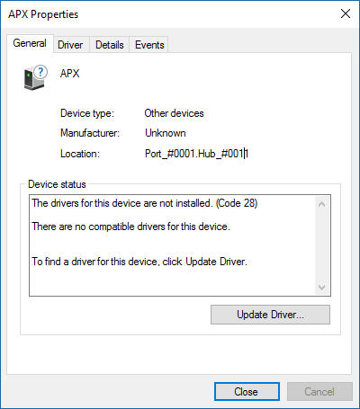
If you have successfully entered the recovery mode the Module will show up as APX device on your development PC. You can now install the APX drivers. The driver is part of NVFlash / Recovery mode package.
This driver works on 32-bit and 64-bit Windows systems.
- Before you start download all the required tools and files:
Earlier NVFlash and batch script were already in the image download package. Do not use them any longer.
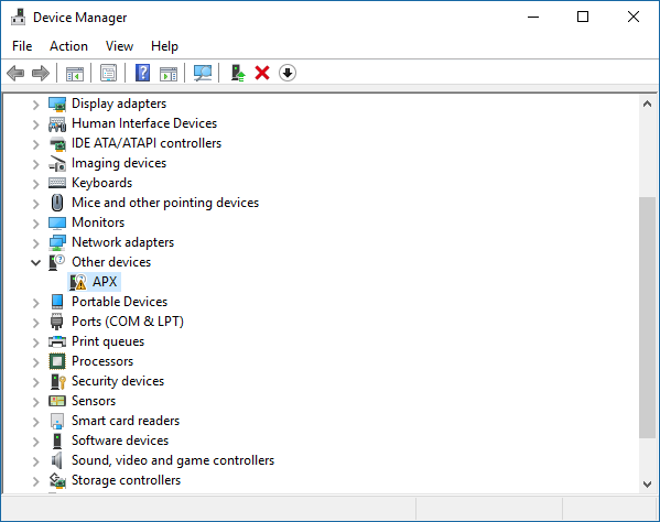
- If you are using the recovery mode for the first time open 'Control Panel' -> Select drop-down box adjacent to 'View by:' and select 'Small icons' -> Click 'Device Manager' in your PC and you should be able to see APX. Refer to the picture below:
- Double-click APX and click Driver tab then Click Update Driver. Refer to the picture below:
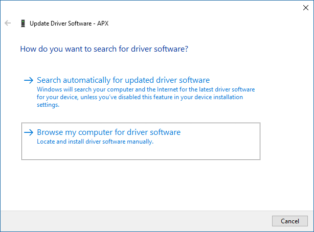
- Choose Browse my computer for driver software. Refer to the picture below:
- Locate and click usbpc_driver_32_64 folder inside NVFlash / Recovery mode package. Refer to the picture below:
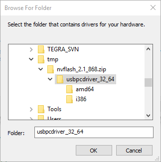
If you get a warning about a unsigned driver, make sure you download the latest signed NVFlash driver (At least nvflash 2.1 868 of the NVFlash / Recovery Toolset).
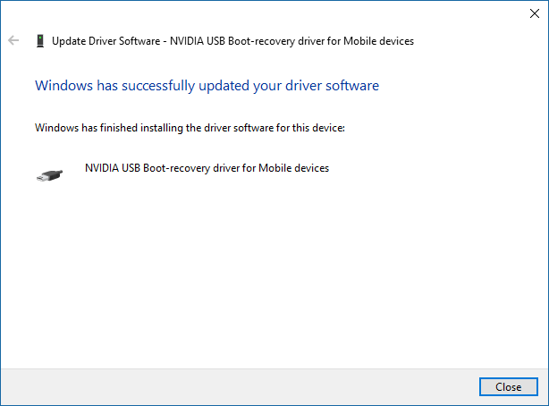
- Upon successful driver installation you will get the following message box. Click Close to close message box. Refer the picture below:
Verify recovery mode
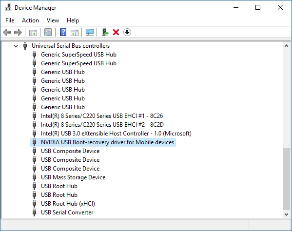
- In order to verify if the recovery driver is properly loaded open Control Panel->Device Manager.
- In Device Manager, you can confirm the successful driver installation by verifying NVIDIA USB Boot-recovery driver for Mobile devices under Universal Serial Bus controllers. Refer to the picture below:
Updating WinCE images
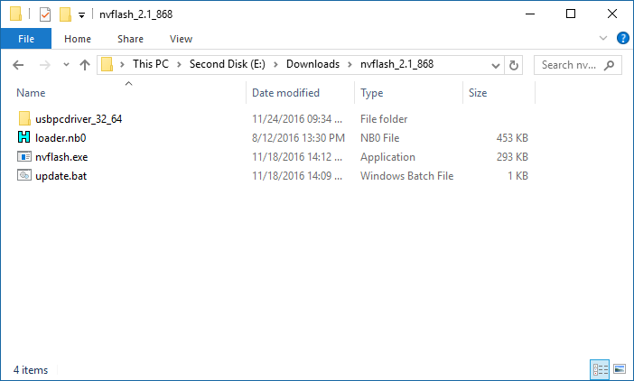
- Open the NVFlash / Recovery Toolset folder. Refer to the picture below:
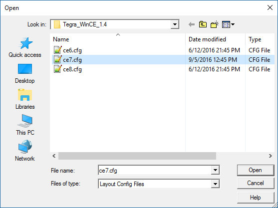
- Double-click update.bat. You are asked to select the .cfg file according to the Windows CE version you want to flash. Locate the .cfg in the Image you downloaded before.
- This will delete all data on the module, including registry, flash file system and config block.
- The module's hardware revision and serial number (mac address) are automatically backed up and finally restored as part of the process.
- Once the image gets successfully flashed you will get the following messages (shown for WinCE7 on Colibri T20).
")
Flashing Embedded Linux Image
- Execute the update.sh shell script as contained in the Embedded Linux demo image packages with the -d (debug parameter) to download U-Boot directly into RAM. On the Colibri T20, additional parameters are required to specify the module type/version: '-r 512' for 512 MB RAM modules and '-v V1_1' for V1.1B or V1.1C modules.
- Then, after inserting a prepared SD/microSD card (as populated with './update.sh -o
<path to card>'), the actual flashing can be initiated on the serial debug console using the 'run setupdate; run update' commands. - Further details can be found in the Flashing Embedded Linux to Tegra Modules article.
Possible Issues
USB_DET Pin (SODIMM Pin 137)
- USB_DET needs to be very close to 3.3V when entering the Recovery Mode. Typically a voltage divider is implemented on these pins. We saw on some customer boards with high impedance voltage dividers that the recovery mode was not working. In these cases, the update utility will display this message and the system will stall:
Do you like to program Windows CE 6 or CE 7?
"Choose 6 or 7"
7
Nvflash version unknown started
rcm version 0X20001
- To fix this problem you need to connect the pin to 3.3V while in Recovery Mode.
- If USB client detection remains an issue even after updating Windows CE, the voltage divider has to be patched with lower resistance resistors.
Specified device is not the boot device
- In case you get the error:
specified device is not the boot device
- Connect the 2 pins directly on the module to enter the recovery mode. Refer to section Directly on Txx module.
- This problem is fixed in the Win CE bootloader V0.1 beta 7 and newer.