HMI Reference Design
Overview
The HMI Reference Design is an HMI Adapter board which goes along with the Viola Plus Carrier Board and extends industrial interfaces like isolated MODBUS, CAN, RS232, Digital I/Os, Buzzer, and Touch Screen Display.
NOTE: Toradex does not manufacture this HMI adapter board. This project is available as open-source.

Features
- 4.3" / 7" RGB TFT Display with our Generic LCD Adapter board V2.0.
- 4 Wire Resistive touch
- 2x Isolated RS485 (D+, D-)
- 1x Isolated RS232 (RXD, TXD, RTS, CTS)
- 1x Isolated CAN (only with Colibri VFxx/iMX6 modules)
- 2x USB HOST (High Speed)
- 1x Full Functional Isolated RS232
- 1x Ethernet (10/100 Mbps)
- Piezo Buzzer
- On-board SPI FLASH memory
- 8x Isolated GPIOs (for extending I/Os)
- Wi-Fi (USB to Wi-Fi Dongle)
- Power supply (7-36V DC)
- Power supply protections - reverse polarity, over voltage, over current, thermal shutdown
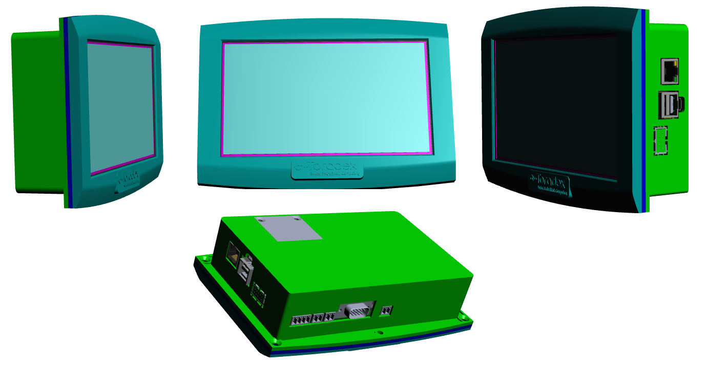
HMI Adapter Board Images
HMI Adapter Board


Viola Plus plugged on HMI Adapter Board

Altium Project
Design Data HMI Adapter Board V1.0
Mechanical Models
Mechanical Models for HMI Adapter Board


The generic STEP model that can be opened and modified in any 3D CAD can be downloaded below.
Mechanical Models for HMI Enclosure
7" HMI Demo Enclosure
4.3" HMI Demo Enclosure
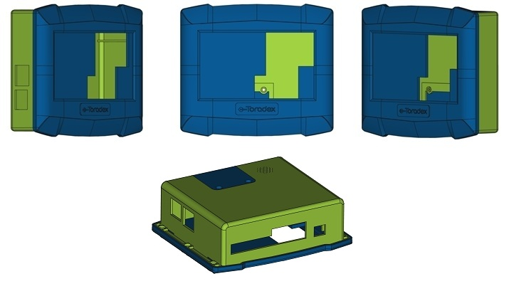
3D step models for the HMI Enclosures can be downloaded below:
Example Application for Colibri VFxx & iMX6* Modules in C#
*PWM 'C' should be used instead of PWM 'D' on Colibri iMX6 module.
(Example application for NVIDIA Tegra based Colibri Modules will be uploaded soon)
HMI Adapter Test Application Screen
Test application can be used to quickly test features provided by the HMI Adapter board.
Prerequisite: Short the Rx & Tx pins of the connector 'X5', Interconnect connectors 'X6' & 'X7' to each other & also, please note that UART 'B' & UART 'C' of the module are used in RS485 mode.
- RS232 Test : Tests the RS232 port of HMI Adapter board(Connector X5).
- MODBUS Test : Tests the MODBUS ports of HMI Adapter board (Connector X6 & X7).
- FLASH MEMORY Test : Tests the on board SPI based Flash Memory.
- Scan GPIOs : Scans the status of isolated GPIOs of HMI Adapter Board. This can be configured for Manual scanning or Automatic scanning through check box.
- Buzzer : Tests the Buzzer of HMI Adapter board.

HMI Adapter Main Application Screen
The main application communicates with externally connected MODBUS I/O cards (Analog I/P, Digital I/P & Digital O/P) over RS485 port of HMI Adapter board 'X6' & provides a graphical user interface.
- 'AI 1' to 'AI 4' Gauges : Shows the 0-5V analog I/P values of first 4 channels of MODBUS AI-08 card.
- 'DI 1' to 'DI 4' Led Indicators : Shows the status of last 4 I/P channels of MODBUS DI-16 card.
- 'DO 1' to 'DO 4' Buttons : Toggles the first 4 channels of MODBUS DO-16 card to "on" or "off".
- MODBUS I/O cards used in reference design are used from Masibus.
- Gauges used in the main application are taken from the evaluation version of iPack from Bee Mobile.
- The LED indicator buttons used in the main application are taken from the evaluation version of Resco MobileForms Toolkit.

Download
Download the example application for VFxx & iMX6* from here.
Please contact support@toradex.cn for more information.