This article talks about the Toradex 
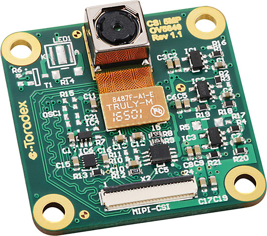
CSI Camera Module 5MP OV5640 plugged into an Apalis Evaluation Board (via the first aka CSI_2_CSI-1/4x FFC receptacle available on the V2.0A versions of our module type specific Apalis mezzanine boards) or starting with the Ixora Carrier Board V1.1A. It is connected via the MIPI Camera Serial Interface 2 (MIPI CSI-2).
On Apalis iMX6 the kernel modules are included out-of-the-box and are loaded by default.
Note: You may need to load a device tree with the correct camera sensor node enabled e.g. for Ixora V1.1A doing setenv fdt_file imx6q-apalis-ixora-v1.1.dtb; saveenv
from within U-Boot.
Camera preview:
gst-launch-1.0 -v imxv4l2src device=/dev/video1 ! capsfilter caps="video/x-raw, width=1280, height=720, framerate=30/1" ! queue ! imxv4l2sink
Assert reset on the OV5640 camera sensor:
echo low > /sys/class/gpio/gpio146/direction
Power-up OV5640 camera sensor:
echo low > /sys/class/gpio/gpio147/direction
Release reset on the OV5640 camera sensor:
echo high > /sys/class/gpio/gpio146/direction
On Apalis T30 the kernel modules are included out-of-the-box. Load camera related kernel modules in this order:
modprobe videobuf2-memopsmodprobe videobuf2-dma-nvmapmodprobe ov5640modprobe tegra_v4l2_camera
Camera preview:
gst-launch -e v4l2src device="/dev/video0" ! 'video/x-raw-yuv, width=(int)640, height=(int)480, format=(fourcc)YUY2' ! nvvidconv ! 'video/x-nvrm-yuv, format=(fourcc)I420' ! nvxvimagesink
gst-launch -e v4l2src device="/dev/video0" ! 'video/x-raw-yuv, width=(int)1920, height=(int)1088, format=(fourcc)YUY2' ! nvvidconv ! 'video/x-nvrm-yuv, format=(fourcc)I420' ! nvxvimagesink
Assert reset on the OV5640 camera sensor:
echo 250 > /sys/class/gpio/exportecho low > /sys/class/gpio/gpio250/direction
Power-up OV5640 camera sensor:
echo 248 > /sys/class/gpio/exportecho low > /sys/class/gpio/gpio248/direction
Release reset on the OV5640 camera sensor:
echo high > /sys/class/gpio/gpio250/direction
On Apalis TK1 the kernel modules are included out-of-the-box. Load camera related kernel modules in this order:
Note: When running NVIDIA's L4T aka Ubuntu ARM you may need to un-load aka rmmod the nvhost_vi
Linux kernel module first which otherwise would conflict with tegra_camera
.
modprobe videobuf2-dma-contigmodprobe ov5640modprobe tegra_camera
Camera preview:
gst-launch-0.10 v4l2src queue-size=1 ! 'video/x-raw-yuv,format=(fourcc)UYVY,width=640,height=480' ! xvimagesinkgst-launch-1.0 v4l2src device=/dev/video0 ! 'video/x-raw,format={UYVY},width=640,height=480' ! xvimagesink
With the Apalis Evaluation Board and an Apalis TK1 Mezzanine V2.0A it is possible to have two cameras running simultaneously. This works by connecting one camera to the first aka CSI_2_CSI-1/4x FFC receptacle and a second one to the third aka CSI_2_CSI-3/2x FFC receptacle available on the Mezzanine.
Assert reset for both OV5640 camera sensors:
echo 250 > /sys/class/gpio/exportecho low > /sys/class/gpio/gpio250/directionecho 195 > /sys/class/gpio/exportecho low > /sys/class/gpio/gpio195/direction
Power on both OV6540 camera sensors:
echo 248 > /sys/class/gpio/exportecho low > /sys/class/gpio/gpio248/directionecho 234 > /sys/class/gpio/exportecho low > /sys/class/gpio/gpio234/direction
Release reset for the second OV6540 camera sensor:
echo high > /sys/class/gpio/gpio195/direction
Move the second OV6540 camera to a different I2C address with this user space aplication:
//${CROSS_COMPILE}gcc ov5640-sccb_id.c -o ov5640-sccb_id #include <stdint.h> #include <unistd.h> #include <stdio.h> #include <stdlib.h> #include <fcntl.h> #include <sys/ioctl.h> #include <linux/types.h> #include <linux/i2c-dev.h> #define OV5640_REG_SLAVE_ID 0x3100 int main(int argc, char argv[]) { char buf[8] = {0}; char filename[20] ={0}; int file; int adapter_nr = 0; / probably dynamically determined / int addr = 0x3C; / The I2C address / int slave_id = 0x3D; if (argc < 4) { printf("usage: %s [i2c-bus] [i2c-addr] [sccb-id]\n", argv[0]); printf("\twhere:\n"); printf("\ti2c-bus: 2 for Apalis T30/TK1, 3 for Apalis iMX6\n"); printf("\ti2c-addr: 0x3C\n"); printf("\tsccb-id: typically other than 0x3C\n"); exit(1); } else { adapter_nr = atoi(argv[1]); sscanf(argv[2], "0x%x", &addr); sscanf(argv[3], "0x%x", &slave_id); buf[0] = OV5640_REG_SLAVE_ID >> 8; buf[1] = OV5640_REG_SLAVE_ID & 0xff; buf[2] = slave_id << 1; } printf("i2c-bus = %d, i2c-addr = 0x%02x, sccb-id = 0x%02x\n", adapter_nr, addr, slave_id); //open the device file snprintf(filename, 19, "/dev/i2c-%d", adapter_nr); file = open(filename, O_RDWR); if (file < 0) { / ERROR HANDLING; you can check errno to see what went wrong / printf("ERROR HANDLING; you can check errno to see what went wrong\n"); exit(1); } //specify device address to communicate if (ioctl(file, I2C_SLAVE, addr) < 0) { / ERROR HANDLING; you can check errno to see what went wrong / printf("ERROR HANDLING; you can check errno to see what went wrong\n"); exit(1); } / Using I2C Write / if (write(file, buf, 3) != 3) { / ERROR HANDLING: i2c transaction failed */ printf("ERROR HANDLING: i2c transaction failed\n"); exit(1); } exit(0); }
Execute this on the module:
./ov5640-sccb_id 2 0x3C 0x3D
Release reset on the first OV6540 camera sensor:
echo high > /sys/class/gpio/gpio250/direction
Load the camera related kernel modules as described above e.g. as follows:
modprobe videobuf2-dma-contigmodprobe ov5640modprobe tegra_camera
Camera preview Camera 1:
gst-launch-1.0 v4l2src device=/dev/video0 ! 'video/x-raw,format={UYVY},width=640,height=480' ! xvimagesink
Camera perview Camera 2:
gst-launch-1.0 v4l2src device=/dev/video1 ! 'video/x-raw,format={UYVY},width=640,height=480' ! xvimagesink
On the hardware revision V1.1 of the ov5640 camera module general improvements were made. These improvements include a dedicated clock generation on the camera module itself. Because of these changes, the CAM1_MCLK is no longer needed. For EMI improvements, CAM1_MCLK may be turned off.
The general approach is to declare the corresponding pad as a GPIO. This will internally switch the multiplexer. As a result, the clock will not be able to leave the SoC. This approach is chosen because CAM1_MCLK is in every processor generated from a clock that is needed in other internal IPs.
Note: The following patches apply for the hardware relevant branches for our BSP 2.8b3.111-20180627.
diff --git a/arch/arm/boot/dts/imx6qdl-apalis-eval.dtsi b/arch/arm/boot/dts/imx6qdl-apalis-eval.dtsi index c06171783e60..3326488dafb1 100644 --- a/arch/arm/boot/dts/imx6qdl-apalis-eval.dtsi +++ b/arch/arm/boot/dts/imx6qdl-apalis-eval.dtsi @@ -246,6 +246,8 @@ ov5640_mipi@3c { compatible = "ovti,ov564x_mipi"; reg = <0x3c>; + pinctrl-names = "default"; + pinctrl-0 = <&pinctrl_cam_mclk_stash>; clocks = <&clks 147>; clock-names = "csi_mclk"; DOVDD-supply = <®_1p8v>; diff --git a/arch/arm/boot/dts/imx6qdl-apalis.dtsi b/arch/arm/boot/dts/imx6qdl-apalis.dtsi index 26c94bd64e51..779a069cedb1 100644 --- a/arch/arm/boot/dts/imx6qdl-apalis.dtsi +++ b/arch/arm/boot/dts/imx6qdl-apalis.dtsi @@ -823,6 +823,13 @@ >; }; + pinctrl_cam_mclk_stash: cammclkstashgrp { + fsl,pins = < + /* CAM sys_mclk */ + MX6QDL_PAD_NANDF_CS2__GPIO6_IO15 0x0000 + >; + }; + pinctrl_ecspi1: ecspi1grp { fsl,pins = < MX6QDL_PAD_CSI0_DAT6__ECSPI1_MISO 0x100b1
Note: On this SoC it is possible to only shutdown the clock CCM_CLKO2
(that will generate CAM1_MCLK). Please note that this clock is also used in the audio subsystem. Turning it off will disable the audio functionality.
diff --git a/arch/arm/mach-tegra/board-apalis_t30-pinmux.c b/arch/arm/mach-tegra/board-apalis_t30-pinmux.c index ae5e82fbedd5..27a2fc0d9ca9 100644 --- a/arch/arm/mach-tegra/board-apalis_t30-pinmux.c +++ b/arch/arm/mach-tegra/board-apalis_t30-pinmux.c @@ -476,6 +476,7 @@ static __initdata struct tegra_pingroup_config apalis_t30_pinmux[] = { } static struct gpio_init_pin_info apalis_t30_init_gpio_mode[] = { + GPIO_INIT_PIN_MODE(TEGRA_GPIO_PCC0, true, 0), }; static void __init apalis_t30_gpio_init_configure(void)
diff --git a/arch/arm/boot/dts/tegra124-platforms/tegra124-apalis-v1.2-gpio.dtsi b/arch/arm/boot/dts/tegra124-platforms/tegra124-apalis-v1.2-gpio.dtsi index e67f79a3c5dd..fc1eb2c1fa00 100644 --- a/arch/arm/boot/dts/tegra124-platforms/tegra124-apalis-v1.2-gpio.dtsi +++ b/arch/arm/boot/dts/tegra124-platforms/tegra124-apalis-v1.2-gpio.dtsi @@ -23,6 +23,7 @@ TEGRA_GPIO(W, 5) /* 152 MMC1_D5 */ TEGRA_GPIO(BB, 0) /* 96 USBH_OC# */ TEGRA_GPIO(BB, 4) /* 262 USBO1_OC# */ + TEGRA_GPIO(CC, 0) /* 224 CAM_MCLK */ TEGRA_GPIO(CC, 5) /* 148 MMC1_D4 */ TEGRA_GPIO(DD, 1) /* 15 Apalis GPIO7 */ TEGRA_GPIO(DD, 2) /* 17 Apalis GPIO8 */